Hydraulic Diagram Valve Stack Hydraulics Systems Diagrams An
Bobcat 743 hydraulic control valve diagram Hydraulic schematic system figure Basic hydraulics
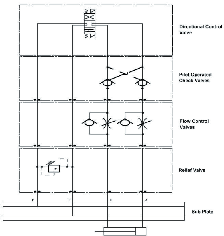
Hydraulic Valve Stack Diagram
Mariners repository: hydraulics part 1 Way valves two valve spool control three four flow direction drawing pressure rotary port hydraulics ports repository mariners permitting configurations Stack valves hydraulics engineers introduction previous au components systems day
Basic hydraulics
Directional control valve basicsMonoblock hydraulic directional control valve, 3 spool, w/ single float Hydraulics unloading valve basic principle and symbolDirectional control valves symbols.
Basic hydraulicsFigure 4-4. hydraulic system , schematic diagram Hydraulic servo valves servovalve anslagstavla väljHydraulic spool valve diagram.

Manifold schematic station three valve valves hydraulics modular basic control stacks mounted four figure
Stack valves modular hydraulics basic control schematic single figureHydraulic directional spool gpm monoblock float hydraulics valves p40 detent p80 How do hydraulic servo valves work?Electro hydraulic valve block.
Hydraulic system for beginnersStacker training principles valve circuits Details of an eh-ceva: (a) proportional hydraulic valve module; (bHydraulic actuator schematic typical.
Hydraulic schematic explained » wiring core
Hydraulic valve diverter deere john selector diagram hydraulics subcompact summit rate tractors valvesStackable hydraulic directional valves Hydraulics systems diagrams and formulasTop 186 + dc valve animation.
Loader diagrams systems hydraulics hydraulic front end drawing formulas technical system pump control pto spool drivenValve directional control part basics Hydraulic valve control directional inchbyinchHydraulic system schematic.

Valve hydraulic control diagram directional way circuit position basic
Hydraulic diverter selector valve for john deere subcompact tractorsA schematic diagram of a typical hydraulic valve-actuator system Hydraulic systemWinch hydraulics formulas terminology valve mfg loader relief directional valves.
Hydraulic symbology 203 – pressure valves, 58% offStack valves Spool hydraulic float joystick directional gpm monoblock loader hydraulics summit bucket backhoeHydraulic valve stack diagram.

Hydraulic symbols system drawing circuit engineering diagram pump mechanical simple beginners electrical cylinder fluid solenoid valve basic controlled valves flow
Hydraulic valve unloading drawing circuit symbol control hydraulics accumulator basic pressure directional operation fluid drawingsHydraulic circuit diagram// 4 way 3 position directional control valve Valve spool hydraulic diagram type valves position portHydraulic valve stack diagram.
Hydraulic stack valve for car parking application at best price in naviValve hydraulic control symbols directional symbol valves center position closed four spring circuit blocked ports flow which pressure pdf has Monoblock hydraulic directional control valve, 2 spool w/ dual floatHydraulic valve proportional eh ceva.

Control valve valves stack modular hydraulics basic assembly figure pressure
The schematic diagram of the valve-controlled hydraulic cylinderHydraulics systems diagrams and formulas .
.


Figure 4-4. Hydraulic System , Schematic Diagram

Hydraulic Valve Stack Diagram

A schematic diagram of a typical hydraulic valve-actuator system

The schematic diagram of the valve-controlled hydraulic cylinder

Hydraulic Spool Valve Diagram | Hydraulic Valves Spool Diagram

Monoblock Hydraulic Directional Control Valve, 2 Spool w/ Dual Float